

Pressure Testing
Excel valves are Unsurpassed for
Accuracy, Reliability and Safety in pressure testing.
In the industries we service the consequences of leaking valves are likely to be severe, therefore product pressure testing is a critical part of the ensuring product integrity. Every customer wants the reassurance that the valves being commissioned on their site have been comprehensively pressure tested. At Excelvalves Services we conduct pressure testing using purpose-built facilities, fully trained personnel and proven procedures to provide you with the confidence that the products supplied are going to perform to your expectations.
Excel valves Services have modern specialist facilities for:
Hydrostatic, Pneumatic, Shell, Seat, and Fire testing.
General Pressure Testing
This test involves filling a valve body with a testing fluid, which is usually water with a corrosion inhibitor. Then, technicians apply pressure over a specific period of time. The time and level of pressure varies depending on factors including the valve material, valve size, and category of pressure test. But in most cases, the pressure level is higher than the operational/working pressure of the valve. Also, the procedure for the pressure test varies depending on the type of valve in question. Generally, pressure tests aim to ascertain the integrity of the valve shell, seat, and seal against leakages due to pressure. After carrying out a test, a valve will not be accepted if the following occurs:
There is any distortion that disrupts the valve operation, due to the test.
Visible leaks anywhere in the valve body/bonnet assembly.
Leakage via static seals (packing) and gasketed joints, except where permitted by design the test standard.
Common industry guidelines for pressure testing valves can be found in ASME B16.34, API 598, MSS-SP-61, API 527, and ISO 5208. Many tests are recorded on paper wheel charts or manually, although digital options are becoming more prevalent.

Hydrostatic Testing
In a hydrostatic test, the valve body is filled with testing fluid and then pressure is applied for a specified length of time. The valve is then inspected for any leakage.
FLUID
The testing liquid can be water, water with a corrosion inhibitor, or another liquid whose viscosity isn’t greater than that of water.
PRESSURE
The testing pressure depends on what material the valve is made of: steel, nickel-base alloy, cast iron, and so on. See the full standard for material-specific hydrostatic test pressures.
High Pressure Gas Testing
Utilising high-pressure pumping systems, valves and other components can be tested underwater at internal gas pressures of up to 9000psi.
Shell Testing
The valve shell refers to the main body of the device. Moreover, its testing in the industry is driven mostly by guidelines from API 598 and ASME B16.34. Typically, the valve is mounted on a test bench and partially opened. Then, the shell is pressurized, with ASME B16.34 recommending a minimum of 1.5 times the valve pressure rating at 100 ℉ (38 ℃) for hydrostatic testing. While that of pneumatic seat testing is 1.1 times the maximum allowable pressure. Pneumatic testing is done to 80-100 psi. Also, both the API and ASME standards recommend varying test duration depending on the size of the valve being tested. The table below summarizes the test duration.
In addition, the test water temperature should range between 41 ℉ (5 ℃) and 122 ℉ (50 ℃). And the pressure gauge used for measurements should have calibration ranging from not less than 1.5 times the test pressure, to not more than 4 times the test pressure. For a valve shell to pass the test, there shall be no visible leakage for the duration of the test.
A valve stem seal (packing) is also monitored during the shell test. For adjustable stem seals, the occurrence of leakage during the test is NOT a cause for rejection, as long as the manufacturer can demonstrate the seal’s capacity to retain at least the maximum allowable pressure of the valve without any visible leakage. Adjustments to the packing are allowed to eliminate leakage. For non-adjustable stem seals, no leakage is permitted during the shell test.
Seat Testing
Typically, the valve seat test is carried out after testing the valve shell. With the same API and ASME standards as with the shell test providing guidance. The recommended pressure is 110% of the maximum allowable pressure at 100 ℉ (38 ℃), and the test time varies with size in accordance with ASME B16.34.
The test duration recommendations from API 598 are similar to these, and it also states the allowable leakage rates from the seat.
For valve sizes greater than 14 inches, the hydrostatic test leakage rate should not exceed two drops per minute per inch. While the pneumatic test leakage rate should be less than four bubbles per minute per inch.
Fire Testing
One of the requirements of industrial valves is having reliable fire protection. This holds particularly true for sensitive applications such as oil and gas, refinery, and petrochemical industries. Moreover, valves in these industries must guarantee a reliable and safe shut-off in case of a fire incident.
In a fire test, a valve is pressurized and subject to high-temperature flames between 1382 ℉ (750 ℃) and 1832 ℉ (1000 ℃) for a period of thirty minutes. During this period, the heat intensity and the leakages – both internal and external – are monitored and measured. Also, after extinguishing the flames and allowing the valve to cool, the technician test its pressure-retaining capacity. All through the test, the leakage levels should be within acceptable limits for the valve to pass as being “fire-safe”. Some key things to note about fire testing include:
Leakages from the piping to valve end connections are not part of the acceptance criteria.
Technicians measure temperature measurement from at least two places. One is 1” (25 mm) from the upper stem packing box on the horizontal centerline, while the other measurement point is 1” below the valve.
Standards such as API 607, API 6FA, ISO 10497, BS 5146, and BS 6755 constitute industry guidelines for fire testing. On the basis of these guidelines, several companies set up their bespoke procedure for fire-safety valves. Of all the fire testing guidelines, API 607 and API 6FA are the most widely used. API 607 provides testing criteria for valves with non-metallic seating and quarter-turn valves. API 6FA provides the testing criteria for metal seated valves.
Note: Most metal-to-metal seated Gates, Globes, and Swing checks are NOT tested to API 607 due to their inherently Fire Safe Design. (There are no soft parts to melt during a fire.)
Fugitive Emissions Testing
A fugitive emissions test aims to assess the impact of gas or vapor leakage from a valve. Although this leakage can be from anywhere along the piping system, statistics show that approximately 60% of fugitive emissions stem from valves. This data highlights the importance of this test. In addition, the impact of these emissions has significant consequences including:
Increase in the risk of fire and explosion.
Economic losses due to leakage of the commodity.
Long-term health risk to the workers and communities in close proximity.
Environmental damage.
When carrying out fugitive emission tests, the most common test gases are helium and methane. The valve is pressurized with the test gas at varying temperatures. Then technicians monitor for leakages via the sniffing or vacuum method. International standards such as API 622, API 624, API 644, ISO 15848-1, and ISO 15848-2 all provide guidance on how to carry out this valve test. However, most organizations develop their specifications to ensure application suitability.

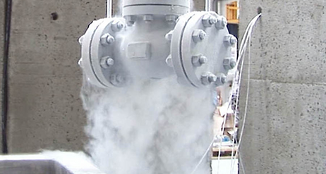
Cryogenic Testing
Cryogenic testing of valves is done for those operating at low temperatures or in cryogenic service. The test procedure involves placing the valve within an insulated tank, with liquid nitrogen at temperatures of down to -320 ℉ (-196 ℃).
Then, helium pressurizes the valve to the operating pressure specified for its class. During the test, technicians closely monitor the temperature inside the valve and leakages. In the end, the valve is depressurized and warmed up until it attains ambient temperature. Thereafter, a detailed report summarizes the performance of the valve and whether leakages were within acceptable limits. There are several international standards that provide guidelines for cryogenic valve testing including ISO 28921-1, ISO 28921-2, EN 12567, and BS 6364.
In addition to the standards mentioned in the previous section, there are a host of standards that provide recommendations for different valve types and test procedures. The table below provides a list of these standards and the areas of testing they cover, for quick referencing.
Applicable StandardValve Type and Test Procedure
Pressure testing Unsurpassed for Accuracy, Reliability and Safety with excelvalves
+91 8531066857
Testings Done at Excel valves
Hydrostatic Testing
High Pressure Gas Testing
General Pressure Testing
Pneumatic Testing
Fugitive Emissions Testing
Fire Testing
Shell Testing
